Kurenniemi Band Pass Filter Banks
In many of his synthesizers (Sähkökvartetti, Andromatic, DICO, and DIMI-A), Kurenniemi used a bank of fixed band-pass filters as the main audio processing phase in the signal path. All banks on different instruments are slightly different and tuned differently.
Kurenniemi liked to tune filters using high-Q settings, typically between 3 and 20. I am not sure why, as building a bank of octave filters with bands much less than an octave can be seen as a weird approach.
Kurenniemi uses an operational amplifier-based multiple feedback band-pass filter topology [1]. DIMI-A uses a UA709 op-amp. Earlier instruments use discrete operational amplifier circuits built from scratch.
DIMI-A 1.4Q

During the Experimental Music Workshop at Aalto University in 2024, we built a more conventional band-pass filter bank for DIMI-A with the participants.
The stock DIMI-A filter uses 160k, 8k2, and 330k as R1, R2, and R3. The capacitors on a single filter are of the same value, and a set of values including 68n, 33n, 15n, 7n, 3n, 1n9, 820p, and 400p is used to create the bands for different filters. These values will give a Q value of 3.2521686010655, which is converted to octaves equal to 0.441881. You can crunch these numbers with an online calculator.
We used the calculator to create a filter that is one octave (1.414Q) wide. This gave us 10k, 3k3, and 22k for R1, R2, and R3. For the capacitors, we used the set of 470n, 220n, 100n, 47n, 22n, 10n, 4n7, and 2n2. This is not the most optimal distribution, but it is close enough, as we used the most available standard capacitor values.
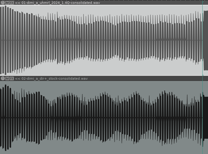
Comparisons between these filters show that 1.414Q filters (top waveform) give output much closer to a square wave than the stock circuit (bottom waveform). The difference is greater at low frequencies but still obvious at higher frequencies. While the 1.414Q filter looks quite close to what you would expect a low-cut square wave to look like, the stock waveforms are somewhat shaky.


We must note that the square wave cannot be fully judged by the appearance of its waveform. Slight changes in the amplitudes and phase shifts of individual harmonics can make the waveform look messy without major audible artifacts.
One question regarding the DIMI-A filter bank and the ultrasonic multiplexer driving the bank has been whether the odd waveforms are a result of filtering or the high-speed splicing of the multiplexer. Based on this experiment, it seems that the process of taking a square wave, splicing it into short bursts, filtering each burst separately, and finally reconstructing the original waveform is possible if the filters are suitable for the job.
Aliasing caused by the multiplexer is quite audible at higher frequencies. You can see this in the picture above, where the shape of every other square is alternating.
Below we see waveform of the recording where all notes are played through from lowest to highest. We can see how the amplitudes of the notes vary when they don’t hit the band perfectly. With a 1.414Q filter, the output is much more even.
When feeding white noise through DIMI (+3dB from Buchla 266), original filter has quite visible peaks on its spectrum.

1.414Q bank gives much smoother results.

While there are obvious benefits in taming the Q values of the filters, having sharper peaks will also have its advantages. One could potentially come up with a circuit where the Q could be controlled in some way.